Crestline Experimental Dive Unit
Additional Circuit Information
about FEOR Light's
Heads Down Display
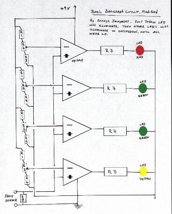
The Circuit Diagram: Basic Bar Graph, Modified
Components used:
Resistors:
R1= 1.5 Meg Ohm
R2= 1 K Ohm Trim Pot
R3= 8200 Ohm (See Notes following)
R4= 4700 Ohm (See Notes following)
R5= 1500 Ohm (See Notes following)
R6= 560 Ohm (See Notes following)
R7= 330 Ohm
R8= 10 K Ohm
Op Amp
NTE 987, Low Power Quad OpAmp,
Light emitting diodes
El Cheapo (from a box of assorted LED's, around 20mA each)
Power Supply
9 Volt DC Battery
Notes:
The values I picked for R3, R4, R5, R6 are really not that important to you concerning this particular project evaluation. You determine your own needs by using the formula for a Voltage Divider. V(out) =V(in) * [ R2 / (R1 + R2) ]
R1 was given above (1.5 Meg Ohm). You determine when you would like various LED's to illuminate, and work the math to solve for R2 in the formula to generate the reference voltages of your choosing. The results of the Voltage Divider formula will determine values for your resistors R3, R4, R5, &R6 . (And if you can't do algebra, you shouldn't....... you should know the rest of the mantra by now.)
The trim pot is not really necessary in the circuit, it just helps to "fine tune" it a little. In reality, the "fine tuning" ability of this circuit is very limited. In fact it was not designed for the purpose of compensation and/or calibration of sensors. It's primary purpose was to test my ability to read basic electronic books, put together a basic circuit, test my design layout and soldering ability, and see how it works in the FEOR during actual ocean dives.
If it is not obvious to you, your sensor puts out some millivoltage corresponding with some PPO2. The output should be somewhat linear. Thus you can compute what the expected millivolt output is at any given PPO2 for that particular sensor. With that information you can select your target PPO2's for each LED. Convert the PPO2 to a millivolt. Calculate what resistors will give you those reference voltages, Apply that reference voltage to the Inverting input of your OpAmp, And you are on your way to your very own custom LED Bar Graph.
The reference voltages that were applied to the inverting inputs of the OpAmps for this project are (approximately)... 6mv for the Yellow LED, 11mv for the First Green LED, 32mv for the Second Green LED, and 47mv for the Red LED. Those values were selected because the oxygen sensor I used put out 10.8 mv reading air. Considering a PPO2 of air to be .208, then the PPO2's corresponding to the illumination of each LED would be PPO2 .12 for Yellow, PPO2 of .21 for First Green, PPO2 of .61 for Second Green, PPO2 .90 for Red. (If a sensor which generates 12.8 mv reading air was used on this circuit, then the PPO2's corresponding to the illumination of the LED's would be .09/.18/.52/.76 for the Y/G/G/R sequence.)
To share a little personal experience, the HDD you see here was designed around a sensor I just happen to have on my desk at the time (which put out that 10.8mv in air). I worked out the values, selected components, arranged the circuit, assembled the circuit, and prepared to dive the unit. Before the dive I made a final check, and low and behold what did I discover? I discovered two things... (1), the LED's came on at a lower PPO2 than designed. (2), the output of the sensor was greater than what my design was based upon. Do you know what happened??? You guessed it. I did all my testing, calculating and other work at home. Home in Crestline, California, at about five thousand foot of elevation. Thus, the output of my sensor reading Air at altitude was less than the output of that same sensor reading Air at sea level. (Yes, I should know that. Guess the rarefied air at altitude got to me. Now you know why I wanted to develop a display that can be utilized "while under the influence". I am easily influenced.)
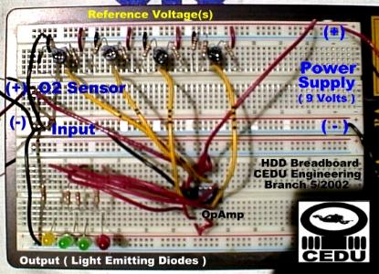
Breadboard of Circuit
More information about Rebreathers/SUBLIME/and the CEDU
can be found starting at
Dr. Bob's The Home Page
"To Swim Is Human, To Dive Is SUBLIME"
And Remember CEDU's Mission Statement:
"To Design, Assemble and Use Homemade Dive Gear While Maximally Stroking Our
Own Ego's and Maintaining the Merest Semblance of Sobriety for the Benefit of
Mankind"